所屬科目:【阿摩】未分類題庫
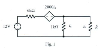
1. (10%) For the circuit shown in Fig. 1, specify the resistance \( R \) that will cause current \( i_{\mathrm{b}} \) to be \( 1.33\mathrm{mA} \) by the method of Thévenin theorem.
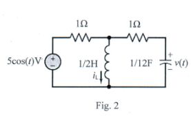
2. (15%) For the \( 2^{\text{nd}} \) order circuit shown in Fig. 2, find the complete response \( v(t) \), including both the components of natural response and forced response, of the circuit for \( t > 0 \) when \( v(0) = 9\mathrm{V} \) and \( i_{\mathrm{L}}(0) = 0\mathrm{A} \).
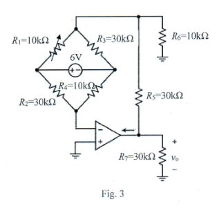
3. (10%) Wheatstone bridge based circuits are often applied in sensor devices and offer possible ways to transfer resistive sensor measurements into electrical signals. A Wheatstone bridge based Op-amp circuit, shown as Fig. 3, was devised to transfer the resistive sensor \( R{1} \) to the output voltage \( v{0} \). Determine the value of \( v{0} \) when \( R{1} = 10\mathrm{k}\Omega \).
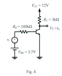
4. (15%) While \( V{C} \) denotes the DC component of the output voltage, \( v{0} \) and \( v{1} \) denote the AC components of the output and input voltages. Determine the small-signal voltage gain \( A{\nu} = v{0} / v{1} \) of the BJT amplifier shown in Fig. 4. Assume the thermal voltage \( V{\mathrm{T}} = 25\mathrm{mV} \), \( V{\mathrm{BE}} = 0.7\mathrm{V} \), \( \beta = 100 \).
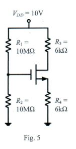
5. (10%) Determine the output voltage \( v{0} \) of the circuit shown in Fig. 5. Assume the threshold voltage of the NMOS transistor \( V{\mathrm{TH}} = 1\mathrm{V} \), its transconductance parameter \( k{n} = \mu{n}C_{\mathrm{ox}}(W / L) = 1\mathrm{mA} / \mathrm{V}^{2} \), and neglect the channel-length modulation effect \( \lambda = 0 \).
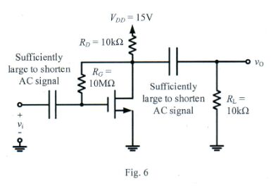
6. (20%) Determine the small-signal voltage gain \( A{s} \) of the MOS amplifier shown in Fig. 6. The transistor has \( V{\mathrm{TH}} = 3\mathrm{V} \), \( k{n} = \mu{n}C{\mathrm{ox}}(W / L) = 0.25\mathrm{mA} / \mathrm{V}^{2} \) and \( \lambda = 0.02\mathrm{V}^{-1} \), and assume that the coupling capacitors \( C1 \) and \( C2 \) are sufficiently large to shorten the AC signals at their frequencies of interest, and \( A{s} \equiv -g{m}R{L} \), where \( R_{L} \) is AC equivalent resistance.
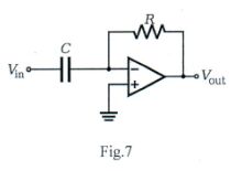
7. (10%) For the Op-Amp differentiator shown in Fig. 7, show the relation between the input and output as:$$V{\mathrm{out}} = -RC \frac{dV{\mathrm{in}}}{dt}$$
8. (10%) Suppose the sinusoidal voltage and current across an circuit component are $v(t) = V{\mathrm{in}} \cos(\omega t + \theta{\mathrm{v}})$ and $i(t) = I{\mathrm{in}} \cos(\omega t + \theta{\mathrm{i}})$, respectively. Show the average power (over a complete period) delivered to the component is$$P = \frac{V{\mathrm{in}} I{\mathrm{in}}}{2} \cos(\theta{\mathrm{v}} - \theta{\mathrm{i}})$$
 阿摩線上測驗
登入